Direct3D - Introduction
In our past examples, we’ve looked at Fixed Function Pipelines and a quick look at the OpenGL shader pipeline. This time around, we’ll take a look at setting up and using DirectX 11.
SharpDX is the underlying library that we’re using for DirectX, as C# doesn’t have a native binding/library for accessing lower level graphics libraries.
DirectX isn’t just a graphics library; it has support for Audio, Direct2D, Input, Fonts, video, etc. However all we’re looking at in this lesson is the graphics side of things.
SharpDX doesn’t abstract out as much as OpenTK does, so we have a fair bit more setup to do in order to be able to just clear a screen. Let’s take it in steps:
Creating the rendering context
SharpDX provides a RenderForm class that handles all the basic windows setup and management functionality.
To initialize D3D, we begin by creating a D3D 11 Device and a D3D Device context. These two interfaces are our abstraction to the video card. So how do we do that?
To create a D3D device, you need to define a swapchain. A swapchain defines:
- The number of buffers used in page flipping.
- How big the buffers should be.
- The format of the backbuffer (color depth).
- Refresh rate.
- The handle to the window
- Windowed/fullscreen
Creating a swapchain looks like this:
mSwapChainDescription = new SwapChainDescription()
{
    BufferCount = 1,
    ModeDescription =
        new ModeDescription(
            mRenderForm.ClientSize.Width,
            mRenderForm.ClientSize.Height,
            new Rational(60, 1),
            Format.R8G8B8A8_UNorm),
    IsWindowed = true,
    OutputHandle = mRenderForm.Handle,
    SampleDescription = new SampleDescription(1, 0),
    Usage = Usage.RenderTargetOutput
};
Now that there is a definition of the swapchain, we need to build the D3D device. It’s pretty simple:
D3DDevice.CreateWithSwapChain(D3DDriverType.Hardware,
    DeviceCreationFlags.None,
    mSwapChainDescription,
    out mDevice,
    out mSwapChain);
For reference: Creating the D3D Device
Next up, we create a device context. From Microsoft:
A device context contains the circumstance or setting in which a device is used. More specifically, a device context is used to set pipeline state and generate rendering commands using the resources owned by a device. Direct3D 11 implements two types of device contexts, one for immediate rendering and the other for deferred rendering.
For this example, we’re going to be working with Immediate contexts.
We also need buffers for the Backbuffer, front buffer, depth buffer. We build the buffers when we resize the window (or are in fullscreen mode and want to change resolutions).
Each buffer has a specific way to be generated:
BackBuffer is acquired from the Swap Chain
mBackBuffer = Texture2D.FromSwapChain<Texture2D>(mSwapChain, 0);
Render Target is created based of the Back Buffer
mRenderView = new RenderTargetView(mDevice, mBackBuffer);
The Depth buffer
mDepthBuffer = new Texture2D(mDevice, new Texture2DDescription()
{
    Format = Format.D32_Float_S8X24_UInt,
    ArraySize = 1,
    MipLevels = 1,
    Width = mRenderForm.ClientSize.Width,
    Height = mRenderForm.ClientSize.Height,
    SampleDescription = new SampleDescription(1, 0),
    Usage = ResourceUsage.Default,
    BindFlags = BindFlags.DepthStencil,
    CpuAccessFlags = CpuAccessFlags.None,
    OptionFlags = ResourceOptionFlags.None
});
The Depth Stencil View buffer
mDepthView = new DepthStencilView(mDevice, mDepthBuffer);
Why do they call it a Render Target and Depth Stencil ‘view’? Microsoft separates the concepts of resources (blocks of memory) and views. A view is just that, a ‘view’ into the data.
Now that all the buffers/views have been created, we need to finalize the binding:
mDeviceContext.Rasterizer.SetViewport(
    new Viewport(0, 0,
        mRenderForm.ClientSize.Width,
        mRenderForm.ClientSize.Height,
        0.0f, 1.0f));
mDeviceContext.OutputMerger.SetTargets(mDepthView, mRenderView);
Loading Shaders
Loading shaders in D3D is actually pretty easy:
mVertexShaderResult = ShaderBytecode.CompileFromFile("example01.fx", "VS", "vs_4_0");
mVertexShader = new VertexShader(mDevice, mVertexShaderResult);

mPixelShaderResult = ShaderBytecode.CompileFromFile("example01.fx", "PS", "ps_4_0");
mPixelShader = new PixelShader(mDevice, mPixelShaderResult);
The input and output of shaders are defined as part of a Shader ‘Signature’. We define that like so:
mSignature = ShaderSignature.GetInputSignature(mVertexShaderResult);
Defining the vertex layout is a little different than what we’ve seen in OpenGL:
mLayout = new InputLayout(
    mDevice,
    mSignature,
    new[]
    {
        new InputElement("POSITION", 0, Format.R32G32B32A32_Float, 0, 0),
        new InputElement("COLOR", 0, Format.R32G32B32A32_Float, 16, 0)
    });
In the Shader file, this binds to the following:
struct VS_IN
{
	float4 pos : POSITION;
	float4 col : COLOR;
};
You can see how the two correlate to each other this way.
Each InputElement defines each element in the input layout - in this case, we’re defining the Position and Color, the format of each position and color are 4 floats. In order, the arguments are:
- The HLSL semantic associated with this element in a shader input-signature.
- The semantic index for the element. A semantic index modifies a semantic, with an integer index number. A semantic index is only needed in a case where there is more than one element with the same semantic. For example, a 4x4 matrix would have four components each with the semantic name matrix, however each of the four component would have different semantic indices (0, 1, 2, and 3).
- The data type of the element data.
- Offset (in bytes) between each element. Use
AppendAlignedfor convenience to define the current element directly after the previous one, including any packing if necessary. - An integer value that identifies the input-assembler. Valid values are between 0 and 15.
Defining a Vertex Buffer
Again, pretty simple - Use D3DBuffer to create the data:
mVertices = D3DBuffer.Create(
    mDevice,
    BindFlags.VertexBuffer,
    new[]
    {
      new Vector4(-1.0f, -1.0f, -1.0f, 1.0f), // Front Vertex
      new Vector4(1.0f, 0.0f, 0.0f, 1.0f), // Front Color

      new Vector4(-1.0f,  1.0f, -1.0f, 1.0f), // Vertex
      new Vector4(1.0f, 0.0f, 0.0f, 1.0f), // Color

      ...

      });
And a constant buffer
We talked about constant buffers in the OpenGL shader tutorial, but to reiterate, a Shader Constant is input from the CPU to a shader. For example, a shader constant for the Model-View-Projection matrix is defined through a constant buffer.
mConstantBuffer = new D3DBuffer(
                    mDevice,
                    Utilities.SizeOf<Matrix>(),
                    ResourceUsage.Default,
                    BindFlags.ConstantBuffer,
                    CpuAccessFlags.None,
                    ResourceOptionFlags.None,
                    0);
The size of the constant buffer, in this example, is defined by the size of a Matrix class - which is the Model-View-projection matrix.
Also note, that in D3D, it’s more common to refer to it as a World-View-Projection matrix, rather than Model-View-Projection. For the rest of this document we will use that notation.
Prepping for Rendering
Time to set up the Device context for rendering:
- Set the input layout
- Set the topology
- Set the Vertex buffer binding (tell the VB what to draw)
- Set the Constant buffer (the World-View-Projection Matrix) to the appropriate constant in the shader.
- Set the Vertex and Pixel shaders
mDeviceContext.InputAssembler.InputLayout = mLayout;
mDeviceContext.InputAssembler.PrimitiveTopology = PrimitiveTopology.TriangleList;
mDeviceContext.InputAssembler.SetVertexBuffers(
    0,
    new VertexBufferBinding(mVertices, Utilities.SizeOf<Vector4>() * 2, 0));
mDeviceContext.VertexShader.SetConstantBuffer(0, mConstantBuffer);
mDeviceContext.VertexShader.Set(mVertexShader);
mDeviceContext.PixelShader.Set(mPixelShader);
Finally Rendering the data
Building matrices if fairly straightforward:
Matrix viewProj = Matrix.Multiply(mView, mProj);
Clearing buffers before rendering:
mDeviceContext.ClearDepthStencilView(
    mDepthView,
    DepthStencilClearFlags.Depth,
    1.0f,
    0);
mDeviceContext.ClearRenderTargetView(mRenderView, Color.Black);
Updating the constant buffer with data:
mDeviceContext.UpdateSubresource(ref worldViewProj, mConstantBuffer);
And then to draw:
mDeviceContext.Draw(36, 0);
And the shader
Shader semantics are fairly similar between GLSL and HLSL. The differences really come down to syntax, more than anything else. For the Vertex Shader, we’ve already seen the format for the input data (the position and the color per vertex) defined. We also see a definition for the input for the Pixel Shader defined like so:
struct PS_IN
{
	float4 pos : SV_POSITION;
	float4 col : COLOR;
};
And then there’s the constant in the shader file, defined for the World-View-Projection matrix:
float4x4 worldViewProj;
Now that we have the data defined, let’s see a vertex shader in action:
PS_IN VS( VS_IN input )
{
	PS_IN output = (PS_IN)0;

	output.pos = mul(input.pos, worldViewProj);
	output.col = input.col;

	return output;
}
Breaking it down line by line, we’re seeing the function signature for the Vertex shader defined as:
PS_IN is the output from the function (the definition is defined earlier), the name of the function, VS and the input arguments into the Vertex Shader VS_IN input.
In the body of the function, we define the output of the function as the variable output - which is of type PS_IN. and we initialize it all to 0.
the next two lines populate both the position and color of the output.
And, like all functions, we return a value, the output variable.
That’s the Vertex Shader. Now, looking at the Pixel shader, it should be fairly obvious what each is doing (to a point).
The function PS returns a float4 - that represents a color of the pixel that we’re trying to render. The input is the result out of the VS function (ergo why it’s called PS_IN - Pixel Shader INput).
So, that only leaves the : SV_Target bit on the pixel shader function definition.
SV_Target is a type of ‘System-Value’ semantics; it’s defined as part of the HSLS compiler. When used in a pixel shader, it describes the pixel location.
To summarize, the vertex shader does nothing more than transform the vertex (and thus the triangle) into screen space and then interpolate the color passed in to the vertex shader across the triangle.
HLSL shader semantics can be found here.
Building a better library
The Shader Class
We want to simplify out coding process by creating several new classes that will allow us to more rapidly create applications. We’ll start out by building out a shader class to work with.
We’ve created a new file, Example02.cs. We still load the same shader file (shaders\example01.fx) but that is now loaded into a Shader class: mShader.
Shader is and IDisposable, so make sure you dispose of it correctly when you use it. There’s a buch of things in there that we aren’t going to be talking about just yet, but patience, we will get to them!
We have multiple Load methods. One expecting an ‘fx’ file, and one that separates out the Pixel and Vertex shaders. I prefer to use separate files for shaders, but that is totally optional. So going forward with other programs, I’ll be using separate files.
The process for using a Shader class is this - create the textual version of the shader (either as a hard-coded string or, as in this method, load the program off disk), compile the shader, set the parameters on the shader, and then call Apply on the shader.
The Cube class
I think we’re all tired of seeing the same code copied and pasted for the sample cube we use, so I’ve generated a Cube class that encapsulates all this. Yes, it’s just a copy/paste of the code that handles all the relevant data and functionality of preparing a cube for rendering. But it will also be the inspiration for other classes later on.
Extending the Cube class
I expect that everyone is familiar with normals. Let’s extend the cube class to contain normals in it’s data. Looking at the class CubeNormals, you can now see that we have vectors that contain the additional normal data.
There’s no special reason why the vertex layout is in [position, normal, color] arrangement. We could easily have set up the orientation in any format we choose. We do, however, have to make sure that the stride of the layout is set correctly. In this case, we’ve added one more Vector4 into the mix, so our stride need to be updated appropriately. I think you can see that updating the stride manually like this is a pain. Once your data format is fairly concrete, you don’t have to worry as much about changing the format. However, it is highly possible that different meshes may have different data requirements (binormals, multiple UV and Color sets …) so you may want to take that into consideration with how you calculate your vertex stride.
We also keep the Input Layout of the vertex data separate from the Cube structure. I’m currently torn on that - it arguably makes more sense to bind it elsewhere; since it uses the VertexShaderSignature, perhaps it should reside in the shader itself? I may change that in a later revision of the Shader class.
Looking at the method for setting the parameters on the shader, you now can see that we’re setting a few more data points - the last three, to be more specific. In this case, we’re looking at a light direction, an ambient color and a diffuse color. This example shows us how to properly set a Lighting ‘Constant buffer’ in D3D. Following into the Shader class, you can see that we have a shader that contains a struct called LightBuffer. It contains 2 Vector4 elements as well as a Vector3 element and a final float called padding.
Why the padding element? And why the [StructLayout(Layoutkind.Sequential)] decorator? Hitting up the MSDN docs gives us a great hint as to why:
link: (https://msdn.microsoft.com/en-us/library/system.runtime.interopservices.layoutkind(v=vs.110).aspx)
Controls the layout of an object when exported to unmanaged code.
Aha. But no, not really. It actually it more related to the attribute LayoutKind.Sequential
The members of the object are laid out sequentially, in the order in which they appear when exported to unmanaged memory. The members are laid out according to the packing specified in StructLayoutAttribute.Pack, and can be noncontiguous.
We don’t want noncontiguous when sending data to our GPU. OK, that’s all fine and dandy, but why the padding?
Rules for packing constant buffers can be a little odd. Constant buffers are expected to align on a 16 byte boundary; the start of a variable in a constant buffer needs to be aligned on a 16 byte boundary. So we add a float into the mix to ensure that if we add another variable at the end of this struct, it comes after the padding and ensures that we’re properly aligned.
The other way of solving this is to be more explicit in how we define our elements in the structure:
[StructLayout(LayoutKind.Explicit)]
public struct LightBuffer
{
    [FieldOffset(0)]
    public Vector4 ambientColor;

    [FieldOffset(16)]
    public Vector4 diffuseColor;

    [FieldOffset(32)]
    public Vector3 lightDirection;
}
Both have their pros and cons. I’ll leave it up to the reader to decide which is best for their needs.
Now that we have the layout of the constant buffer, we need a BufferDescription for that buffer:
BufferDescription lightBufferDesc = new BufferDescription()
{
    Usage = ResourceUsage.Dynamic,
    SizeInBytes = Utilities.SizeOf<LightBuffer>(),
    BindFlags = BindFlags.ConstantBuffer,
    CpuAccessFlags = CpuAccessFlags.Write,
    OptionFlags = ResourceOptionFlags.None,
    StructureByteStride = 0
};

mLightConstantBuffer = new D3DBuffer(device, lightBufferDesc);
and to put data into this buffer for the shader to use:
DataStream mappedResourceLight = default(DataStream);
device.ImmediateContext.MapSubresource(mLightConstantBuffer, MapMode.WriteDiscard, MapFlags.None, out mappedResourceLight);
mappedResourceLight.Write(lightBuffer);
device.ImmediateContext.UnmapSubresource(mLightConstantBuffer, 0);

device.ImmediateContext.PixelShader.SetConstantBuffer(0, mLightConstantBuffer);
Texturing
Rendering stuff isn’t very useful if you can’t texture it. This next bit covers some fairly simple aspects of loading and using textures in D3D
First thing first, let’s look at our new model class, CubeTextureNormals. From it’s name, you can probably tell what it contains: positions, normals, and … textures?
Well, not really, ‘textures’, but texture UV coordinates. Simply put, UV coordinate sets define where, in ‘texture space’ a vertex would fall on a texture. Texture space is defined between 0 and 1 and starts at the top left of a texture.
For example:
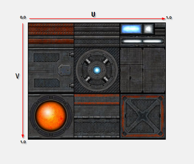
For our needs, we are only using 2D coordinates (yes, you can have 3D textures). Applying a triangle onto the texture can be visualized like so:
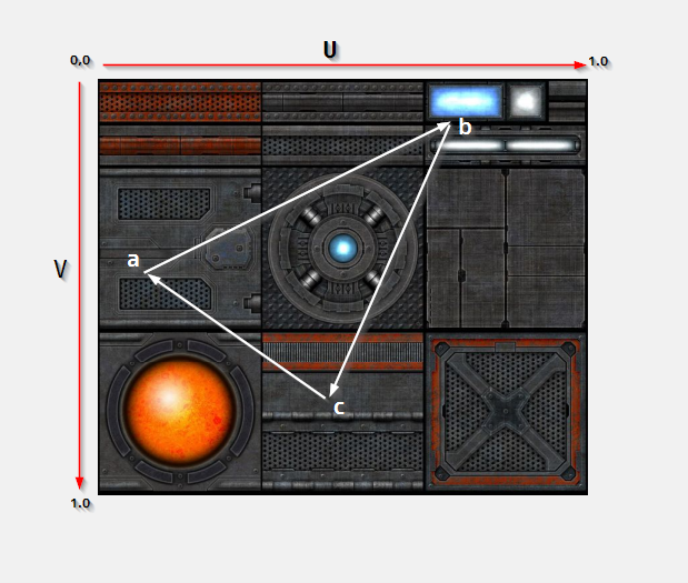
Points a, b and c would have corresponding UV values mappeed against the texture. Nothing crazy there. I’ve coded them by hand (you’re welcome) but you’d want to use a proper 3D DCC package to do it right. There are also various projections you could use to automatically generate the UV coordinates onto regular shapes, but that’s beyond the scope of this article.
Now that you have UV data for your content, we need to load some textures to use! To that end, I’ve created a Texture class we can use. There’s really nothing surprising here. SharpDX has access to the ‘Windows Imaging Component’; a Microsoft API that gives us access to some fairly low level functionality for reading/writing image data. (link: https://msdn.microsoft.com/en-us/library/windows/desktop/ee719902.aspx). The big takeaway here is that WIC allows us to read pretty much any image data type.
Note: as an exercise to the reader, there is an intentional bug here. Where is it? What does it do? How do you fix it?
The takeaway from this class is that we want to provide to D3D a ShaderResourceView that maps a Texture2D. That resource is then fed into a ‘Sampler’ that can do many, many things to a texture. I won’t go over all the grubby details of that, aside from the fact that allows for interpolation between pixels of an image, or combination of pixels in an image, depending upon how close/far from a triangle the viewer is.
You create a sampler using a SamplerStateDescription and a SamplerState. The SamplerStateDescription is just that, a description object that says how to create the SamplerState. From the MSDN, the SamplerState:
Sampler state determines how texture data is sampled using texture addressing modes, filtering, and level of detail. Sampling is done each time a texture pixel, or texel, is read from a texture. A texture contains an array of texels, or texture pixels. The position of each texel is denoted by (u,v), where u is the width and v is the height, and is mapped between 0 and 1 based on the texture width and height. The resulting texture coordinates are used to address a texel when sampling a texture.
link: (https://msdn.microsoft.com/en-us/library/ff604998.aspx)
I do want to go into much more detail on this, but Jay is looking to talk more about SamplerStates and different types of filtering. I’m going to park this topic here until he has a chance to talk about it.
Just like everything else we’ve done, we need to let the D3D pipeline know what’s going on. We enable a sampler like so:
mDeviceContext.PixelShader.SetSampler(0, mSampler);
And we update the shader to now take a ShaderViewResource that maps to our texture:
mShader.SetShaderParam(mDevice, new Vector3(0.0f, 5.0f, 5.0f), mTexture.TextureResource, new Vector4(1.0f, 1.0f, 1.0f, 1.0f), new Vector4(0.1f, 0.1f, 0.1f, 1.0f), ref world, ref viewProj);
And in the shader, we take that ShaderResourceView and apply it to the pixel shader (the vertex shader doesn’t use it at all)
public void SetShaderParam(D3DDevice device, Vector3 lightDirection, ShaderResourceView texture, Vector4 ambientColor, Vector4 diffuseColour, ref Matrix world, ref Matrix viewproj)
{
...
   device.ImmediateContext.PixelShader.SetShaderResource(0, texture);
}
But that’s not all!
One other thing that we do in Example04 is break down the transformation matrices passed into the vertex shader. Previously we’ve been combining all the matrices into a world-view-projection matrix. However that may not be useful in the long run. When we have multiple objects, you may want to pre-computer the view-projection matrix, but the world matrix will change from object to objet (they all won’t be transformed into world space - the GPU is better at doing that).
So, we have a MatrixBuffer, laid out very similarly to the LightBuffer!
[StructLayout(LayoutKind.Sequential)]
internal struct MatrixBuffer
{
    public Matrix world;
    public Matrix viewproj;
}
No padding necessary here.
Sending this across to the GPU is, again, fairly straightforward:
device.ImmediateContext.MapSubresource(mMatrixConstantBuffer,
                                       MapMode.WriteDiscard,
                                       MapFlags.None,
                                       out mMappedResourceMatrix);
mMappedResourceMatrix.Write(matrixBuffer);
device.ImmediateContext.UnmapSubresource(mMatrixConstantBuffer, 0);

device.ImmediateContext.VertexShader.SetConstantBuffer(1, mMatrixConstantBuffer);
However, we do have to have a bit of glue code on the shader side of things. The definition of that buffer in the vertex shader looks like so:
cbuffer MatrixBuffer : register(b1)
{
    matrix world;
    matrix viewproj;
}
The register(b1) tells the HLSL shader compiler what constant buffer register (or ‘slot’) to use for reading the data. In the C# side, that maps to the ‘1’ in
device.ImmediateContext.VertexShader.SetConstantBuffer(1, mMatrixConstantBuffer);
The layout of the register keyword can be found here: (https://msdn.microsoft.com/en-us/library/windows/desktop/dd607359(v=vs.85).aspx)
Shader model reference link: (https://msdn.microsoft.com/en-us/library/windows/desktop/bb509638(v=vs.85).aspx)
Something sort of resembling a framework (Example05.cs)
No, it’s not really a framework now, but it’s starting to look more an more like one. Yes, it’s still another spinning cube, but the cube, this time, was generated in Maya, not by hand. Thus we now have a rudimentary RenderMesh class that holds a renderable object.
So, a RenderableMesh has a D3DBuffer for vertex data, only reads Triangles (no index buffer at this point), and also contains a RenderMaterial class instance. For a lot of you, this is old hat, especially if you’ve worked in any 3D DCC, but a Material in this case defines color information that should be applied to a mesh. Typically that includes an ambient color, specular, diffuse … textures … it really depends on your shading model. For this case, though, we’re going to use a fairly simple shading model; ambient color, diffuse color and a diffuse map. In a later example, we’re going to do much, much more complex shaders.
However, we need to be able to load data from an intermediate file format. In this case, .fbx (although other formats are supported). Are we going to write our own import library? Hell no. There’s a fantastics Open Source library out there for both C++ and C# called Open Asset Import library: (https://github.com/assimp)
Yes, it’s called AssImp. Shut up.
What I’ve done is created a static class called MeshManager that tracks loaded meshes (so you don’t re-load an existing mesh) and provides a RenderMesh for you. It uses the AssImp library to do all the heavy lifting. What we do with that library is access all the vertex and material data and generate the RenderMesh and RenderMaterial from it. There are a few convenience functions in there (building a proper path to the assets, including textures), as well as some data validation.
But there is a lot more it can (and will) do. Loading an asset from an fbx, dae or other file format is not a quick process. It’s fairly complex. Also, intermediate file formats are large. They don’t have to be. Especially considering what we want as data. So the actual goal of this tool class will be to eventually generate a ‘transform’ of an intermediate data file into a highly compact and potentially streamable version of the data, in binary form. But more on that later (much later).
To that end, I’ve also updated the Shader as well - the constant buffer for the LightBuffer hasn’t changed, but we’ve broken the MatrixBuffer down even further to contain the world, view and projection matrices. This is far from optimal, but there’s a reason for this madness.
See, as I was building Example05, I was having a heck of a time getting the object transformation just right. So I broke the matrices down into their individual components so I could better debug them - make sure that what I was sending in was what I was expecting.
“But wait!” you say, with baited breath. “It’s a shader. How can you debug shaders! In C#!”.
Well, you don’t debug them. In C#. You debug them in the graphics debugger. And in Windows 10. if you’re on Windows 7, you may be SOL.
If you’re in dev studio and start up the ‘Graphics Debugger’, you’re in for some win!
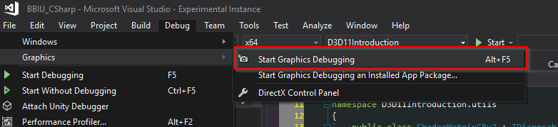
And that starts up the graphics debugger! (BTW - totally available in the community edition of VS!)
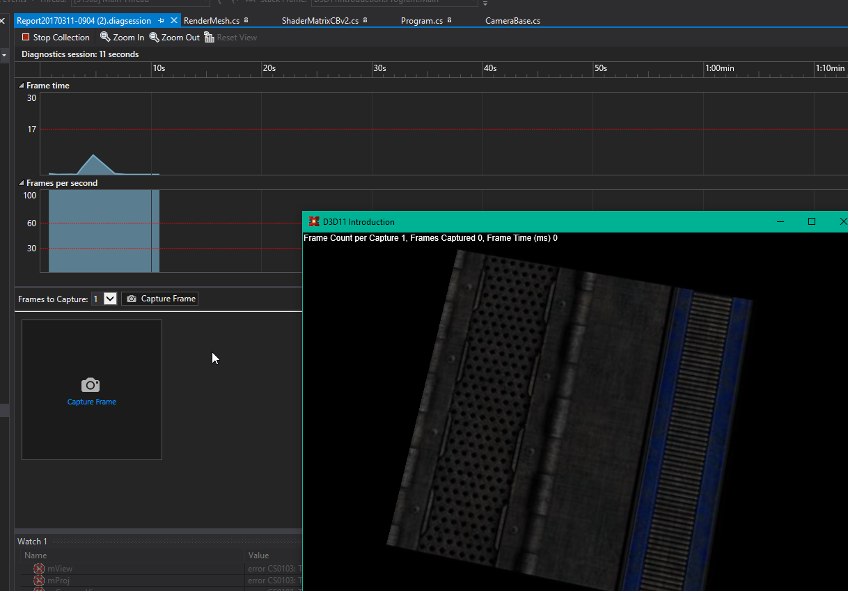
Grabbing a sample of what’s going on? Press the ‘Capture Frame’ button:
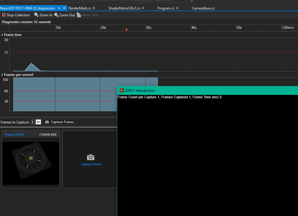
Once you’ve snagged some frames, you can now start debugging what’s going on. There’s a lot in here, and I won’t cover it all here. But I’ll hit the highlights.
Let’s inspect a captured frame:
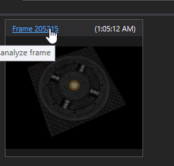
That opens up a whole other debugger!
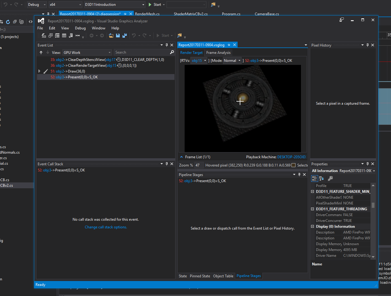
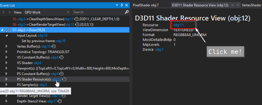
In the ‘Event List’ window, you can see all the D3D calls that have been invoked. Expand the ‘Draw’ item in it:
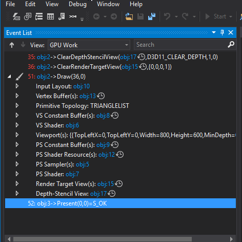
and then click on, say, the Input Layout item:
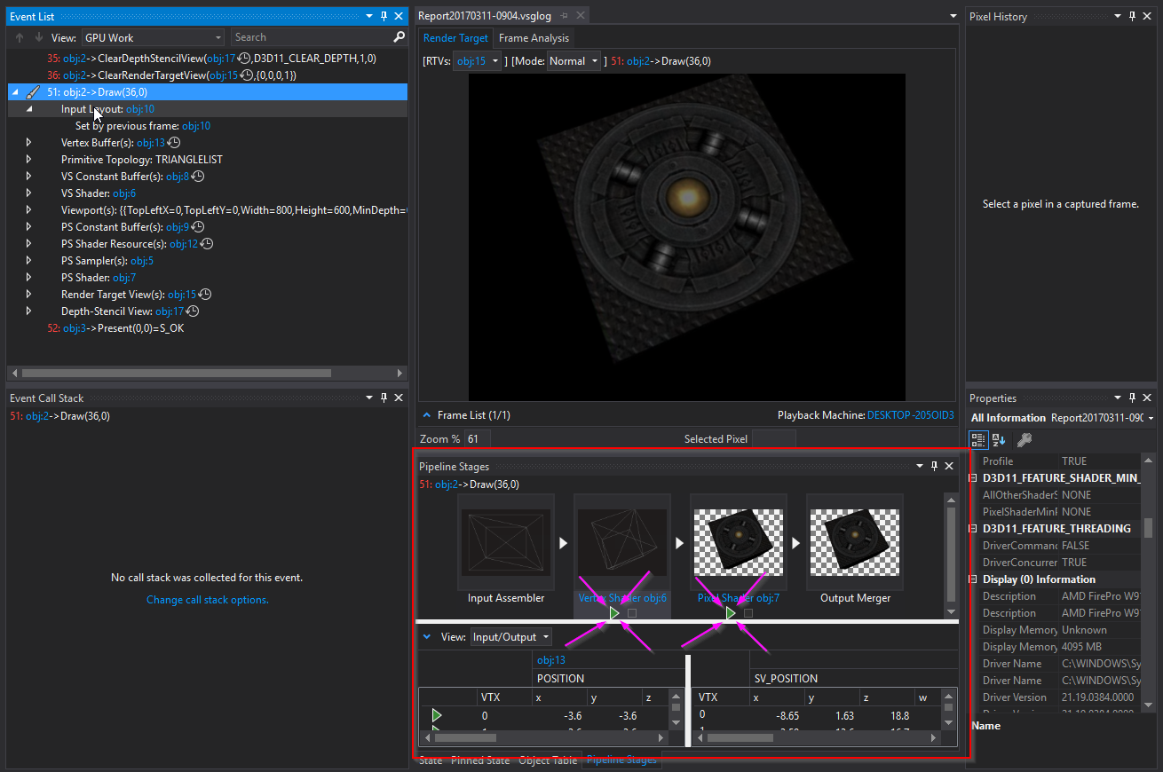
The arrows pointing to the two buttons? Those are the vertex and pixel shader debuggers. When you click on them, they simulate what happens in the appropriate shader. Go ahead and click on the vertex shader ‘play’ button.
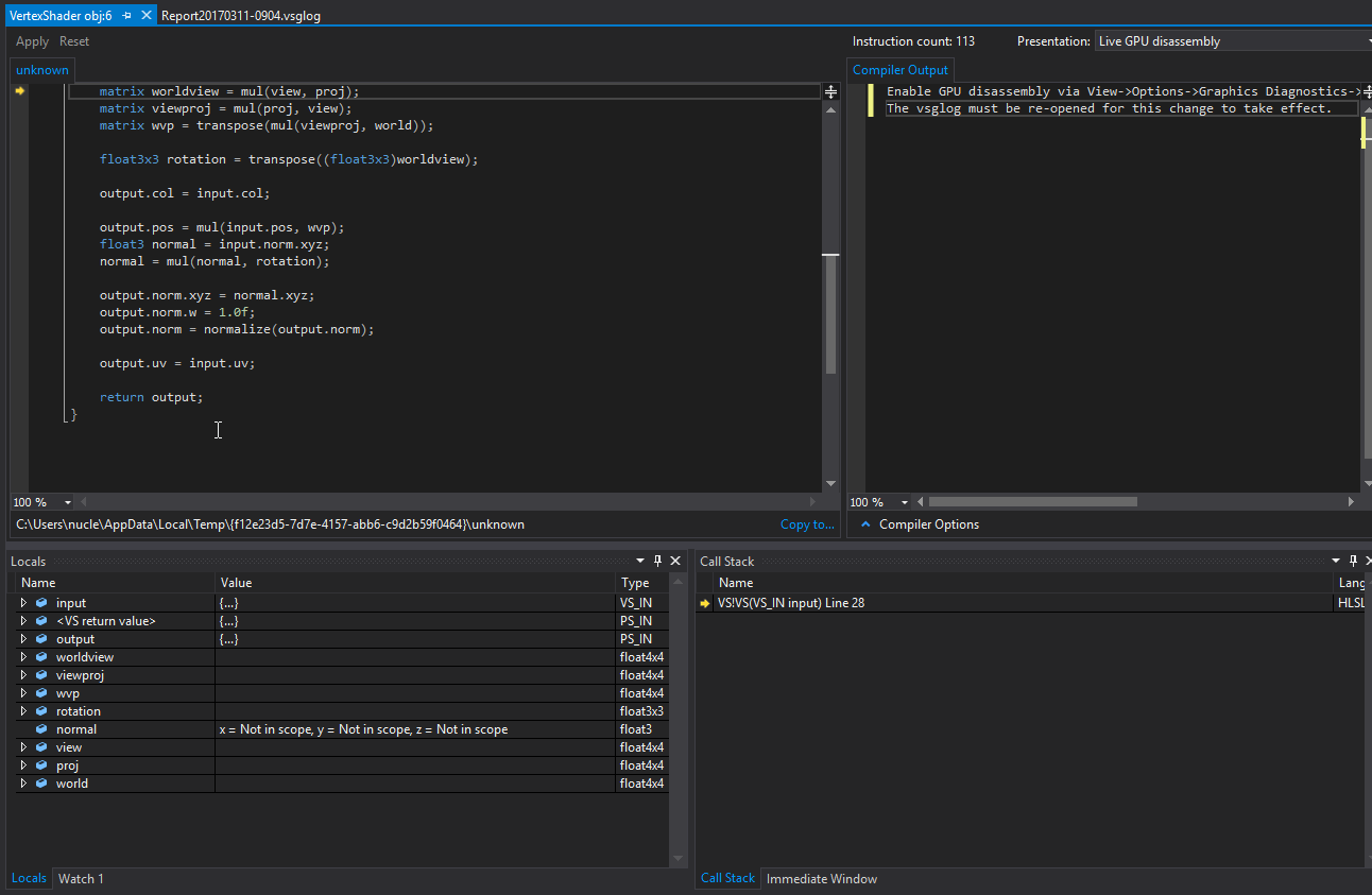
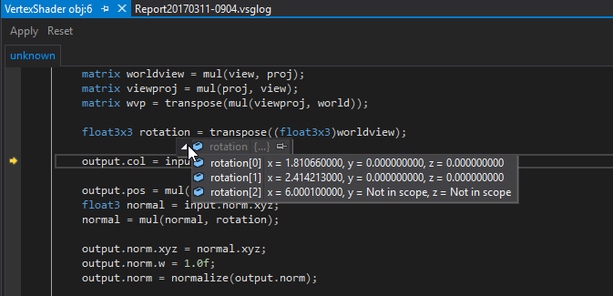
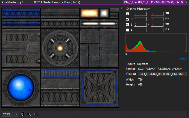
That is an honest to god debugger for your vertex and pixel shader. You can set breakpoints, inspect variables. You can’t change values to see what happens, but it is a great way to figure out what’s where and what values are being processed.
You can also inspect and see what are in constant buffers
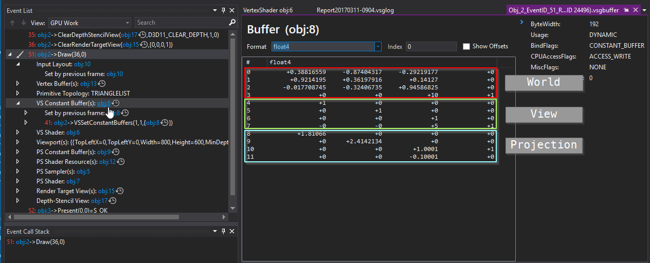
So, as you can see, we’ve actually got some decent debugging tools with D3D and Visual Studio, out of the box. We’ll explore these tools more as we progress along our merry little way.
A couple of notes
The shaders that we use here are fairly lightweight. They’re also un-optimized.
I don’t mean, I haven’t witten them optimally (I haven’t, but that’s because I’m being purposely verbose). I’ve disabled compilation optimizations on the shaders so that the above debugger has better data for being able to debug them.
I’ve done this in the shader compiler:
public bool Load(D3DDevice device, string vsData, string psData)
{
    if (device == null || vsData == string.Empty || psData == string.Empty)
    {
        return false;
    }

    mVertexShaderResult = ShaderBytecode.Compile(vsData, "VS", VertexShaderVersion, ShaderFlags.Debug | ShaderFlags.SkipOptimization);
    mPixelShaderResult = ShaderBytecode.Compile(psData, "PS", PixelShaderVersion, ShaderFlags.Debug | ShaderFlags.SkipOptimization);

    return (mVertexShaderResult.ResultCode == Result.Ok) &&
            (mPixelShaderResult.ResultCode == Result.Ok);
}
Specifically, using the following flags:
ShaderFlags.Debug | ShaderFlags.SkipOptimization
In production code, you’ll want to remove them or replace them with something more appropriate.
And a camera to round out this mess
In Example06 I finally introduce a camera class into the mix. It encapsulated the View and Projection matrices, exposes accessors for them and updates the camera based on input.
I’m cheating a fair bit here and using OpenTK’s input library to get the camera up and running. I will eventually move away from this and use DirectInput (or whatever D3D 11 is calling it these days). This camera is essentially a near-verbatim copy of the previous OpenGL camera I created, replacing all the matrix operations with the comparable D3D calls.
Also note that I’m using a Left Handed co-ordinate system. Who says you need to use a Right Handed co-ordinate system!
#Summary
That’s pretty much it for an intro. We’ll dig further into D3D in a future lesson, exploring lighting models and different material systems. And with that, I’m out!