OpenGL - An introduction to a more modern approach
In the previous section, we discussed the legacy OpenGL programming model (more commonly referred to as the ‘Fixed Function Pipeline’). In this next section, we’re going to investigate a more modern approach, that utilizes shaders, Vertex buffers, Index buffers and how to send data to shaders from your program.
To further assist, I’ve created a Google Sheets document here:
To start - a more proper framework
In the Introduction project, a lot of things were put together hapdash. I’ve made that better in the ShaderIntroduction project (but there’s still work to be done):
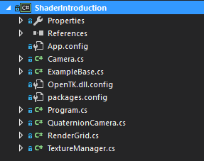
A fair bit has changed with this codebase. I’ve been a bit more regimented in how these classes were defined. They’re also a bit more generalized and properly reusable. Some things to note:
- The
ExampleBaseclass Contains aCameraby default. It is never Updated (I may change this) so it is up to the derived class to update the camera. - The
Cameraclass is a fairly rough FPS-style camera. I will be cleaning this up as we go. However, theCameraclass also maintains the Projection matrix, as well as the View matrix. Traditionally, cameras maintain that information. TextureManageris extracted into it’s own class. This will not be used in this lesson (currently), but is going to be used in later lessons.- The same goes for the
RenderGridclass.
In our previous codebase, we were using a more ‘legacy’ based version of OpenGL; this is the fixed function version of OpenGL that does not support shaders. In this example, we’re going to start talking about using proper shaders. We’re not going to touch on Texturing in this introduction. What we are going to cover, consists of:
- Vertex and Index buffers.
- Setting up data.
- Setting up and creating simple shaders.
- Sending data to shaders.
- Rendering.
This is a surprising amount of material to cover and our once-simple applications from the first lesson are going to become significantly more complex.
What is a Vertex buffer?
In our Legacy pipeline (from lesson01), we defined geometry data through using a set of OpenGL state calls to
    GL.Begin(primitve)
       GL.Color()
       GL.VertexN()
    GL.End()
This if far from optimal, considering that for a large amount of data, it never changes. So we can define a ‘buffer’ of data - in this case a buffer of Vertex data. That goes into what OpenGL calls a Vertex Buffer Object or VBO. Wikipedia defines a VBO as
A Vertex Buffer Object (VBO) is an OpenGL feature that provides methods for uploading vertex data (position, normal vector, color, etc.) to the video device for non-immediate-mode rendering. VBOs offer substantial performance gains over immediate mode rendering primarily because the data resides in the video device memory rather than the system memory and so it can be rendered directly by the video device. These are equivalent to vertex buffers in Direct3D.
However, in modern OpenGL, it is just a buffer of data. It has no inherent structure as far as OpenGL is concerned; you can put whatever the heck you want into it. It is up to a shader program to evaluate the contents of that buffer.
If there is no inherent structure to the data, then how does it work? Let’s walk through a simple example (which is what we use in the current codebase). Let’s assume that right now the only data we want to work with is triangle data. A triangle consists of three vertices: X, Y and Z. We also want to colourized the triangle, so each vertex will have a color component (R, G, B, A). So for each vertex element, we are going to have something that looks like this:
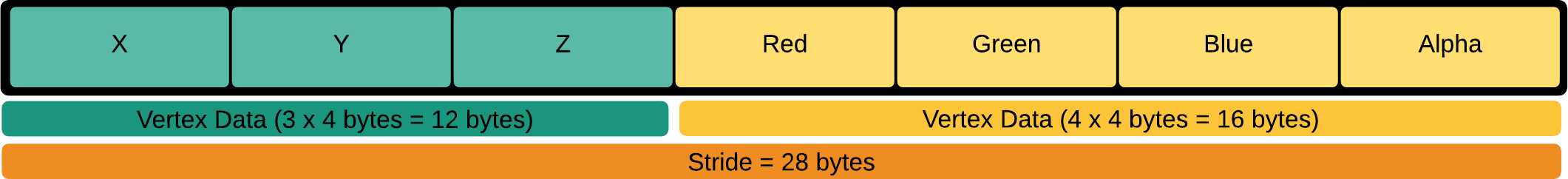
What we’re saying here is that we’re using 12 bytes (3 floats @ 4 bytes/float) to define the positional data of a vertex and 16 bytes (4 floats @ 4 bytes/float) for the color component. This results in a total of 28 bytes for the total data per vertex. This is called the Stride of the vertex data. What we have done here is created an interleaved data format. We end up with data that looks like this:
[V][C][V][C][V][C][V][C] …
The stride defines how far we have to jump to get to the next block of data (eg: once we’ve read the first vertex, to get at the next vertex, we have to jump N bytes to read the next vertex … if we skip the color data).
We can also store the vertex attribute data in ‘blocks’, and thus not interleaving the data. Like so:
[VVVV…][CCC…]
Using an interleaved format is probably the most performant, but there are always exceptions to the rule. So why is it the most performant overall? From Wikipedia:
Interleaved data formats cause less GPU cache pressure, because the vertex coordinate and attributes of a single vertex aren’t scattered all over in memory. They fit consecutively into few cache lines, whereas scattered attributes could cause more cache updates and therefore evictions. The worst case scenario could be one (attribute) element per cache line at a time because of distant memory locations, while vertices get pulled in a non-deterministic/non-contiguous manner, where possibly no prediction and prefetching kicks in. GPUs are very similar to CPUs in this matter.
It’s also not just VBOs that you’re interested in. You will also want to create an Index Buffer (OpenGL calls these Element Buffer Object or EBOs). So, what is an EBO? What do we need these for? Let’s do a simple example to illustrate:
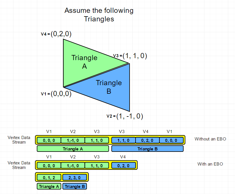
So, what we’ve done is essentially reduce the amount of data that we need to represent a mesh. If we store the data as pure triangles, with duplication, we end up with 2 Triangles x 3 vertices x 3 floats(x,y,z) x 4 bytes/vertex (no color information in this case) - 72 bytes (168 bytes if we include color). However, using an index buffer, we reduce that to 4 vertices x 3 floats x 4 bytes/vertex - 48 bytes. Adding the index buffer into the mix is 6 indices x 4 bytes - 24 bytes. But that’s assuming 4 bytes/index. Which we really, REALLY don’t need to use. Remember, a uint gives us a grand total of 4,294,967,295 / 3 (1,431,655,765 triangles). I fear the day we need almost 1.5 billion triangles for games. So we could use half that (a ushort for instance) to get 65,000 triangles.
However, just in case you think it isn’t that much of a saving. Let’s assume you have a 50,000 triangle mesh. And you have the standard 28 byes/vertex.
50000 x 3 x 28 = 4,200,000 bytes
It’s really hard to say what kind of loss we’d get because it really depends on the mesh geometry, but let’s assume a fully connected mesh where each triangle adds only one additional vertex.
   ( 50000 + 3 ) * 28 = 1,400,084
   50000 * 3 indices * 2 bytes/index = 300,000
   Total: 1,700,084
The less data we need to transfer, the better. The math may be off, but you can see a couple of additional improvements here as well - we don’t have to duplicate vertices! Instead of an additional 3 floats to represent 1 vertex, we simply add 1 uint to point the an existing vertex in the VBO.
How do you go about creating a VBO? I’ve encapsulated the core functionality of a VBO in the VertexBuffer class. The process can be broken down into the following:
- Determine the layout of your vertex data. In this case, I’ve already done that.
- Create a data store to transiently hold the data. This is the data your application will track. You’ll also promote this to OpenGL. In the case of our example, we create a
floatarray that can hold all the data. If your data is not of a consistent data type (ie: you may use a mix of doubles, floats, even ints), you may want to use a struct array instead. - Create a data store for your EBO.
- You’ll need to have OpenGL create a VBO and EBO buffer for you. Like all buffers in OpenGL, a buffer is represented by an integer value. That ID is written into
mVertexBufferObjectID. - Populate the VBO and EBO with data.
- Do Render Stuff (Purposely left high level at this point).
Generating VBOs and EBOs
First off, we need a place to store the data. in VertexBuffer, we have two members:
    protected float[] mVertexData;
    protected uint[] mIndexData;
This is just a way to temporarily hold the data until we can push it up to the graphics card. Populating this array is nothing fancy - check out AddTriangle, AddVertex and AddIndex.
So, to create a VBO and EBO:
GL.GenBuffers( numBuffersToGenerate, buffersGenerated)
But all that does is create a buffer. Now that we have a buffer, we can start working with the data. Remember, OpenGL still works like a state machine, even though it’s ‘Modern’ OpenGL. Now that we have a buffer ID (the Buffer ID is called a buffer object name), we can start working with it.
    GL.BindBuffer(bufferTargetType, bufferName)
    GL.BufferData(bufferTargetType, size, data, usage)
    GL.BindBuffer(bufferTargetType, bufferName)
What do we have now? If done right, we have a buffer for Vertex data and a buffer for index data.
How do we render this? That’s where shaders come in.
Vertex Shaders
I’m going to start off with the technical side of loading up a shader first. After that, more details on the shaders themselves and how we end up getting data into the shaders.
First off, we need some way of creating shaders. Instead of hard-coding it, we’re going to load it from a text file. It’s part of the project, so it gets copied into the output folder.
Loading the shaders is fairly straightforward, we use the File.ReadAllText() function to pull in all the text from the shader.
Now that we have the shader text, we need to compile the shader. Just like the VBOs and EBOs, we need to create a Shader Named object.
    VertexShaderID = GL.CreateShader(ShaderType.VertexShader);
    FragmentShaderID = GL.CreateShader(ShaderType.FragmentShader);
Now we have shader ID to work with. It’s time to compile the shader:
   GL.ShaderSource(VertexShaderID, VertexShaderSource);
   GL.CompileShader(VertexShaderID);
   GL.GetShaderInfoLog(VertexShaderID, out info);
   GL.GetShader(VertexShaderID, ShaderParameter.CompileStatus, out statusCode);

   if (statusCode != 1)
   {
      Console.Write(info);
      throw new ApplicationException(info);
   }
We have to compile two shaders, one for the vertex shader and one for the fragment shader. The shaders, working together constitutes a Program. So we need to create a program and attach shaders to it:
    Program = GL.CreateProgram();
    GL.AttachShader(Program, FragmentShaderID);
    GL.AttachShader(Program, VertexShaderID);

    GL.LinkProgram(Program);
    GL.UseProgram(Program);
Now that we have the shader program created and the shaders loaded, we can now render the data. However, we now need to talk about shaders.
Vertex Shaders
Let’s take a look at the shader itself.
    #version 400
    layout (location = 0) in vec3 vertex_position;
    layout (location = 1) in vec4 vertex_color;

    uniform mat4 mvp_matrix;

    out vec4 color;

    void main(void)
    {
        color = vertex_color;
        //ref line 124
        gl_Position = mvp_matrix * vec4(vertex_position, 1.0);
    }
OK, a couple of things to dig into here. Aside from the GLSL version decorator (the #version 400), the next two lines define the data that we are expecting to get from the vertex buffer. So the first bit, the layout (location = 0) in vec3 vertex_position; reads like this
layout(qualifier1, qualifier2 = value, ...) variable definition
What the layout qualifier does is allow the C# code (CPU code) to not have to directly bind the vertex attribute to the item in the stream (it’s done with a call to GL.GetAttributeLocation()and GL.BindAttrLocation()). Otherwise, without those calls, the GLSL compiler assumes that the vertex layout matches what’s defined in the shader - the first attribute in the vertex layout specification is the position, the second attribute in the vertex layout is the color (remember, it’s a 0 based index).
The next line defines the Model-View-Projection matrix. This is sent in from the CPU side (C# code). The code looks like this:
    // This is not the actual code, but a more verbose version.
    Matrix4 ModelViewProjection = ModelViewMatrix *
                                  WorldMatrix *
                                  ProjectionMatrix;

    GL.UseProgram(shaderProgram);
    int mvpLocation = GL.GetUniformLocation(mBasicShader.Program, "mvp_matrix");
    GL.UniformMatrix4(mvpLocation, false, ref ModelViewProjection);
    GL.UseProgram(0);
So we use a specifc shader program with GL.UseProgram(ProgramID) and disable it by calling the same method, but with a 0 argument.
Sending data to the shader program, in this case the Model-View-projection matrix is done through two functions: the first one to get a variable ID from the program (in this case the mvp_matrix variable) through GL.GetUniformLocation(). Then, once we have the variable ID, we can set the data (in this case, it’s a uniform matrix) through GL.UniformMatrix4(). Whatever we set in this variable is the value the shader will use.
At this point, it’s all on the shader:
- We define an output, that is used in the next shader stage. In this case, the
out vec4 color; - We define the shader entry point, the
mainin C-language speak. - We set the output color that we just defined to the color passed in by the vertex buffer
- we then modify the vertex postion (
vertex_position) passed in on the vertex buffer why the MVP matrix and assign it to a variable calledgl_Position.
Where did that gl_Position variable come from? It’s actually defined as part of OpenGL’s vertex, tessellation evaluation and geometry languages. It’s part of a global instance of the gl_PerVertex named block. It is an output that receives the homogeneous vertex position; the position of the vertex in screen space. See khronos.org for a deeper breakdown. In other words, the GLSL vertex shader doesn’t output any data, but it does allow us to populate global data in each shader stage.
OK. What do I mean by ‘each shader stage’. We’ve danced around this a bit. This shader we’ve just looked at? I’ve repeatedly called it the ‘vertex shader’. That’s arguably the first stage in the shading pipeline. However there’s a lot more to it than that.
Personally, I love this diagram from (http://antongerdelan.net):
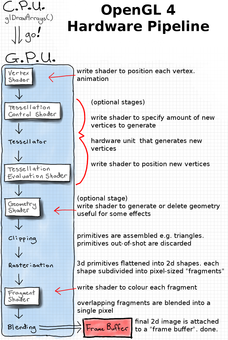
In all honesty, Anton’s site does a fantastic job talking about the broad aspects of shaders. I’ll try to do justice and dig a bit deeper into them and how we’re using them.
Fragment/Pixel shaders
As we’ve seen in the above diagram, we’ve only touched on Vertex shaders. There’s one last piece of the puzzle, and that’s Pixel/Fragment shaders. I’ll probably end up slipping and call them Pixel shaders more often than Fragment shaders, but I’m using them interchangeably.
If you look at our C# code, you’ll notice that we don’t do anything with sending data to Pixel shaders. That’s because all the data we’re sending right now is generated in the Vertex shader. In a later article, I’ll introduce how we would do that.
So, the entire purpose of a pixel shader is, in all honesty, exactly that - how to shade pixels. Adding a color value to a pixel on the screen.
From the vertex shader, we saw that we set the color output value to that of the vertex color:
color = vertex_color;
This color is fed into the pixel shader (interpolated across the triangle).
In the Pixel shader, we don’t actually do a lot:
    #version 400

    layout (location = 0) out vec4 frag_color;

    in vec4 color;

    void main(void)
    {
        frag_color = color;
    }
It’s incredibly simple - we set an output value bound to the pixel. In fragment shaders, you can think of this as the index of the output buffer that we are writing the pixel to. If we don’t define one in out CPU code (C# code), and we weren’t to explicitly add the (location=0) bit to our shader, if there is only one out variable, the compiler will normally generate one for us. But don’t do that.
Thus, we’re only writing out the interpolated color from the fragment shader. That’s it. Nothing terribly fancy. In a later lesson, I’ll go over more.
I think that’s enough for this lesson. It’s been a lot to write, as we’re covering a lot of fundamentals. The rest of the code is fairly self-explanatory.
Until next time!