OpenGL - 2D and Legacy 3D (Fixed Function beginnings)
Welcome to the first part of 3D programming in C# using OpenGL (and OpenTK by extension).
In this series I’ll talk a fair bit about some 3D math basics, but the real focus of this article series is to help you build and
understanding of the underlying tech and process that goes on under the hood to get pixels to the screen.
The structure of the introductory project is one source file Program.cs that you can swap out ExampleNN classes to see different
implementations of concepts.
OpenGL 2D
A few things to note about OpenGL.
- OpenGL works like a state machine. You set the state of something and it stays set until you change it.
- There’s a “Legacy”, fixed function API that doesn’t require shaders. We’ll start there.
- There’s a new shader based version.
- There’s also a new, Vulkan set of extensions. Vulkan is a ‘new’ way of rendering, much closer to console style development.
So, where to start? Let’s assume a few things.
- You understand some basics regarding 3D spaces.
- You have some understanding about texture formats and creating C# applications. + You understand C#, creating applications and windows development.
- You may have worked with Maya, 3D Max or another DCC package.
Let’s put some pixels (in the form of a triangle) onto the screen.
To do that, we first need to create the rendering device. OpenTK handles the majority of that for us. If you really want to see what goes on
at the truly lowest level (binding a window to an OpenGL context, preparing the rendering buffers, etc) there are a great number of C++
tutorials online and this topic is outside of the scope of this series.
All of the examples that I’ll show are Console applications - they don’t have a typical window that’s generated (like a WPF app). OpenTK
does all of that for you using a class called GameWindow. So, I’ve created a base class called ExampleBase that does the majority of the
setup for you. It initializes the window (at 1024x768, 32 BPP with a 16 bit Depth/Z buffer).
abstract class ExampleBase : GameWindow
{
    public ExampleBase() : base(1024, 768, new OpenTK.Graphics.GraphicsMode(32, 16, 0, 0))
    { }
Just in case you aren’t aware, let’s do a quick review of some things here.
- Once we create a window, the actual drawing area (what’s called the canvas), is where we end up using as the drawable area. That area will have a colour depth, in this case it’s set to 32 bits per pixel (2^32 number of colours can be displayed).
- Next, we define a Depth, or Z-buffer. This allows us to determine the distance of a pixel from the camera. More on that in a bit.
- We’ll talk about the other numbers later.
Next, I’ve overloaded the OnLoad method to update the window title and then do this:
GL.ClearColor(0.0f, 0.0f, 0.0f, 0.0f);
What this does is set the the colour that we use to clear the screen to a specific RGBA value (in this case, full black). This is part of that whole State Machine setup I mentioned earlier; once this value is set, it stays set until it’s changed.
As part of the GameWindow class, there is a method that is called each frame called OnRenderFrame. I overload this method with a call to my own internal method CustomRenderFrame where each derived class can do it’s own logic. Here’s the code:
protected override void OnRenderFrame(FrameEventArgs e)
{
    base.OnRenderFrame(e);

    CustomRenderFrame(e.Time);

    base.SwapBuffers();
}
Finally, we need some simple keyboard handling. So on the OnUpdateFrame override, we use the OpenTK library Input to get the state of the keyboard (or, alternatively, the mouse or joystick) to process input devices. In this case, we’re just checking to see if the escape key has been pressed.
OK, so that’s a rapid look at the basics. It’s overly simplified, but you can easily research the rest to cover the gaps if need be. You can also ask questions and I can add more detail as need be.
Lesson 01 - Example 01: Putting a pixel on the screen.
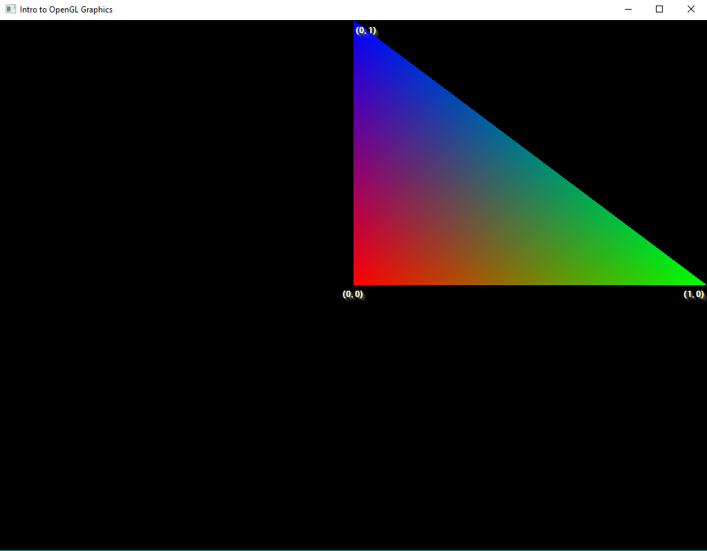
Now that we have the ability to build a window, the drawing area that is made available to us is in a ‘normalized’ view. The coordinate system of the window ranges from (-1,-1) to (1,1) with (0,0) being the the center of the window. We’ll call this the ‘Display Coordinate System’.
Let’s experiment with that, with Example01. In this example, we want to draw one triangle onto the screen. Why a triangle? That’s because outside of lines and points, triangles are the base building blocks of 2D and 3D graphics. OpenGL does define other Primitive types (like quads), but they are collections of triangles.
In the class Example01 we are going to draw a triangle in the window, using the Display coordinate system. To do this, we’re going to use the OpenGL commands Clear, Begin, Color and Vertex.
First off, every frame we need to clear the screen (and any other buffer used in the rendering process). There’s a couple of buffers that we can clear. We’ve already defined a 32 bit colour buffer (what we render to) as well as the Depth buffer. That’s what the following call does:
GL.Clear(ClearBufferMask.ColorBufferBit | ClearBufferMask.DepthBufferBit);
Next up, we begin the actual definition of the data to be rendered. We do this by first defining the primitive type we want to define. In this case, we want to define a set of triangles, or a single triangle (in this case). We do this like so:
GL.Begin(BeginMode.Triangles);
So what we’ve done is define a state for the data that is coming down the pipe next. We continue feeding that data until we tell OpenGL that we’re not sending any more data, with an End call.
GL.End()
In between the Begin and End calls, that’s when we send the triangular data to OpenGL. This is where the commands Color and Vertex come into play. So, if we do the following:
{ // Not necessary, just in place for clarity
    GL.Color3(1.0f, 0.0f, 0.0f);
    GL.Vertex2(0,0);

    GL.Color3(0.0f, 1.0f, 0.0f);
    GL.Vertex2(1, 0);

    GL.Color3(0.0f, 0.0f, 1.0f);
    GL.Vertex2(0, 1);
}
I think it’s fairly obvious what those commands are doing, but to be safe
GL.Color3() defines and RGB colour state that is to be used for every subsequent vertex fed into OpenGL via the GL.Vertex2 call. And thus we end up with the following output.
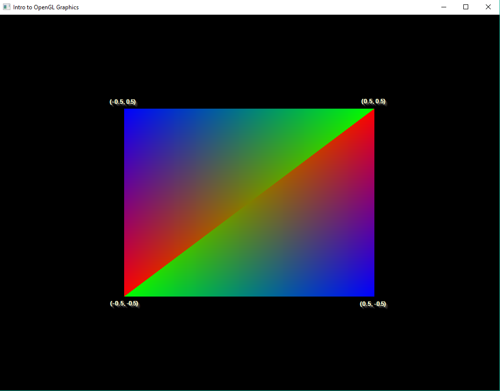
Lesson 01 - Example 02: Getting an idea of sizing
With that simple little example out of the way, let’s continue with something a little more - throwing a couple of triangles on the screen to see the real extents of the Display coordinates. Essentially, the rendering code looks like this:
GL.Clear(ClearBufferMask.ColorBufferBit | ClearBufferMask.DepthBufferBit);

GL.Begin(BeginMode.Triangles);

{ // What happens when you change the vertex positions?
    GL.Color3(1.0f, 0.0f, 0.0f);
    GL.Vertex2(-0.5f, -0.5f);

    GL.Color3(0.0f, 0.0f, 1.0f);
    GL.Vertex2(-0.5f, 0.5f);

    GL.Color3(0.0f, 1.0f, 0.0f);
    GL.Vertex2(0.5f, 0.5f);

    GL.Color3(1.0f, 0.0f, 0.0f);
    GL.Vertex2(0.5f, 0.5f);

    GL.Color3(0.0f, 0.0f, 1.0f);
    GL.Vertex2(0.5f, -0.5f);

    GL.Color3(0.0f, 1.0f, 0.0f);
    GL.Vertex2(-0.5f, -0.5f);
}

GL.End();
From this, we end up with the following:
Lesson 01 - Example 03: Blending triangles
Everyone knows what transparency is. Implementing it in OpenGL in the fixed function pipeline is fairly easy. First off, we need to enable a specific feature in OpenGL - Blend. To do that we call
GL.Enable(EnableCap.Blend)
That tells OpenGL to enable Blend mode. Now we need to determine what type of blending we’re going to use. There’s lots of differnt types of blend functions, but for now, let’s start with
GL.BlendFunc(BlendingFactorSrc.SrcAlpha, BlendingFactorDest.OneMinusSrcAlpha);
What does that do? The OpenGL blend function is defined here. What it tells us is that the first parameter defines the blend function for the source pixel (the triangle we’re drawing) vs the second parameter (the destination pixel).
Given the current parameters, the source pixel’s Alpha is used in the alpha test. Then the destination’s alpha value is used (1-alpha). These are essentially scalars that are multiplied against the color values, both in the source and destination pixels and then the results are added together. I’ll leave that as an exercise to the reader to work through the math.
Lesson 01 - Example 04: Drawing without using the painter’s algorithm
If you’ve been plaing around with rendering your own triangles, you may have noticed that we’ve only been using Vector2 functions to draw triangles. We’ve been doing this because we only needed 2 dimensions worth of data. However, what would happen if we used Vector3 values? If we go that route, we end up using World Coordinates. From a cartesian standpoint, we end up with the following:
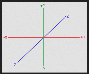
Remember that the camera is looking down the Z axis. This means that from the camera perspective Z increments positively towards the camera and negatively away.
So, in our next example, we do the following:
protected override void CustomRenderFrame(double delta)
{
    GL.ClearDepth(1);
    GL.Clear(ClearBufferMask.ColorBufferBit | ClearBufferMask.DepthBufferBit);

    GL.Begin(BeginMode.Triangles);
    {
        GL.Color3(1.0f, 0.0f, 0.0f);
        GL.Vertex3(-0.75f, -0.75f, 0.5f);

        GL.Color3(0.0f, 0.0f, 1.0f);
        GL.Vertex3(-0.75f, 0.75f, 0.5f);

        GL.Color3(0.0f, 1.0f, 0.0f);
        GL.Vertex3(0.75f, 0.75f, 0.5f);

        GL.Color3(1.0f, 1.0f, 1.0f);
        GL.Vertex3(0.0f, 0.0f, 0.75f);

        GL.Color3(1.0f, 1.0f, 1.0f);
        GL.Vertex3(0.0f, 1.0f, 0.75f);

        GL.Color3(1.0f, 1.0f, 1.0f);
        GL.Vertex3(1.0f, 0.0f, 0.75f);
    }
    GL.End();

}
First, we clear our depth buffer (it gets cleared to 1). Then we draw two sets of data - one triangle at a Z depth of 0.5f and the other at a depth of 0.75f. And they look like they are displaying correctly (and, of course they are). But what happens if you change the order? Like so:
GL.Begin(BeginMode.Triangles);
{
        GL.Color3(1.0f, 1.0f, 1.0f);
        GL.Vertex3(0.0f, 0.0f, 0.75f);

        GL.Color3(1.0f, 1.0f, 1.0f);
        GL.Vertex3(0.0f, 1.0f, 0.75f);

        GL.Color3(1.0f, 1.0f, 1.0f);
        GL.Vertex3(1.0f, 0.0f, 0.75f);

        GL.Color3(1.0f, 0.0f, 0.0f);
        GL.Vertex3(-0.75f, -0.75f, 0.5f);

        GL.Color3(0.0f, 0.0f, 1.0f);
        GL.Vertex3(-0.75f, 0.75f, 0.5f);

        GL.Color3(0.0f, 1.0f, 0.0f);
        GL.Vertex3(0.75f, 0.75f, 0.5f);

}
GL.End();
We end up (hopefully) with different results as before. what we end up seeing is that the order in which we present the data to the renderer matters. This is commonly known as the ‘Painters Algorithm’. We can’t always assume that we can sort the triangles before sending them to OpenGL. So we use the Depth buffer to determine if the pixel to be rendered should be consumed or discarded. In order to enable that, we need to enable the Depth test. That’s fairly simple to do:
protected override void OnLoad(EventArgs e)
{
    base.OnLoad(e);
    GL.Enable(EnableCap.DepthTest);
    GL.DepthFunc(DepthFunction.Lequal);
}
Adding this code and reverting your original changes should result in the triangles being rendered correctly.
When we get into more ‘proper’ 3D, we’ll discuss how the depth buffer works in conjunction with the projection matrix.
Lesson 01 - Example 05: Drawing using textures
This will cover a bit more content including:
- How to load a texture and OpenGL’s Texture functions
- Mipmapping
- UV coordinates
How do we load up a texture to feed into OpenGL? We can use the standard bitmap class to read in the data. The problem is, how do we pull the bits in the bitmap into OpenGL? We can access the bits of a bitmap with the LockBits method. This gives us a BitmapData that we can use to copy the image data into OpenGL.
Normally we keep a reference or pointer to reuse later. In OpenGL we use numerical IDs to identify resources. We’ll create a TextureID using the GL.GenTexture() method. We then use the GL.TexImage2D() method to copy the image data into the Texture resource.
The last thing we want to do is set up our texture filtering and generate mipmaps. What are Mipmaps? It’s a way to increase speed when you’re using a textured triangle at a distance.
Think about it, when you are rending a texture where the pixels of the triangle are smaller than what they would be in the source image, we don’t need all that extra data. So we would want to use a smaller version of the image. Which is what a mipmap functionally is. But not just one image, but a cascading pyramid of scaled textures.
See the wikipedia article for more information.
That’s what my LoadTexture() and LoadImage() methods do. Once we have the texture loaded, we generate the mipmaps for that texture with the GL.GenerateMpimaps() method.
The last thing is that I’ve created a ContentPipeline class that holds a dictionary of strings and IDs. The goal here is to keep from re-creating the same texture resource - we simply key a resource to the filename.
Finally, when we want to draw a textured polygon we need to initialize OpenGL to use textures. In Example05 I’ve updated the class to enable textures like so:
protected override void OnLoad(EventArgs e)
{
    base.OnLoad(e);

    GL.Enable(EnableCap.Texture2D);

    // Load up any resources we need
    mSampleImageTextureID = ContentPipeline.LoadTexture("resources/SampleImage01.png");
}
Now that we have a Texture ID in the mSampleImageTextureID variable, we can use that when rendering our next triangle. In order to render a textured triangle, instead of (or in addition to) using GL.Color4(), we use GL.TexCoord2() to define the texture coordinate for the vertex.
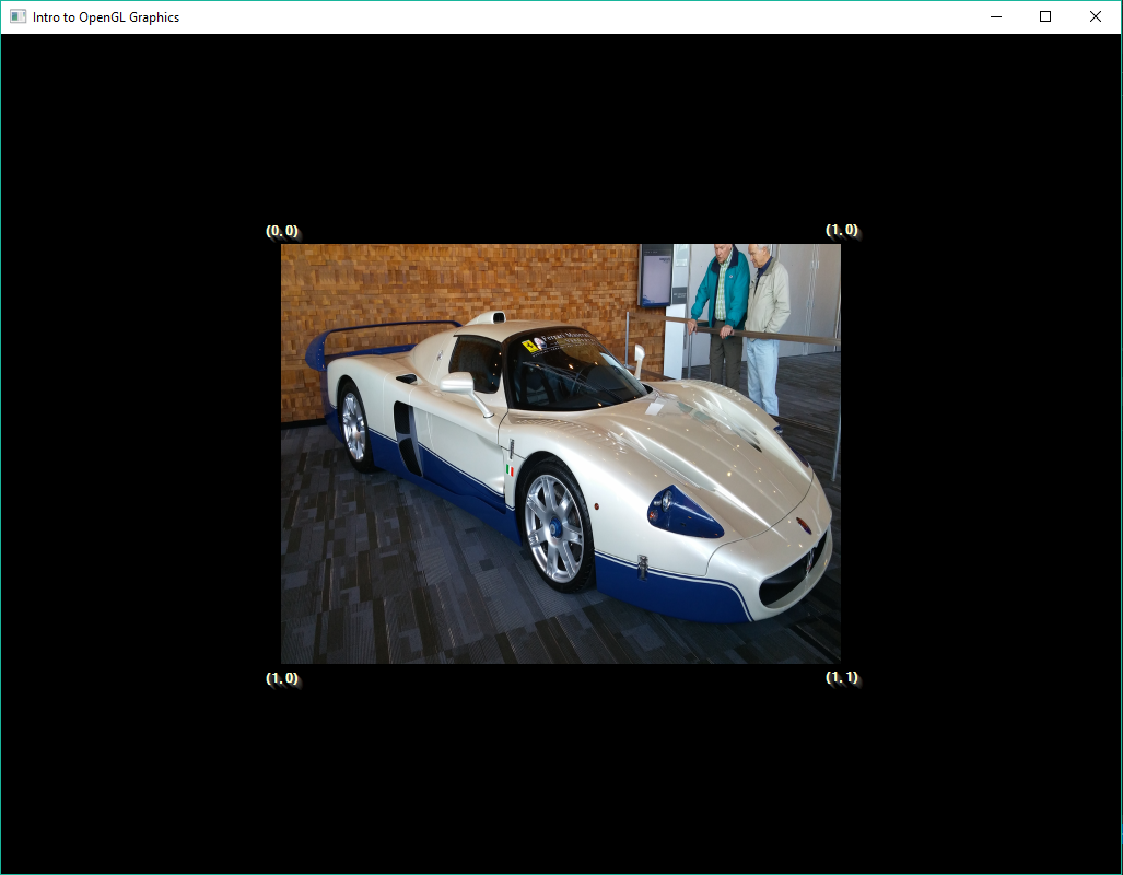
So what does that mean, Texture Coordinate lookup? Essentially for every Vertex that we have, we can look up a color value for it in a texture. Much like the colors that you saw in the previous examples, a linear look up is done on that texture as well.
So, this is the source image:

So, when we want to render triangles with a texture, we need to provide a lookup into the image. This is what the UV coordinate are used for. The coordinate set ranged from (0, 0) to (1, 1). That’s the top left of the image and to the bottom right of the image.
So, if we draw a square (two triangles sharing an edge), like so:
GL.ClearDepth(1);
GL.Clear(ClearBufferMask.ColorBufferBit | ClearBufferMask.DepthBufferBit);

GL.BindTexture(TextureTarget.Texture2D, mSampleImageTextureID);

GL.Begin(PrimitiveType.Triangles);
{
    GL.Color4(1.0f, 1.0f, 1.0f, 1.0f);

    GL.TexCoord2(0.0f, 0.0f);
    GL.Vertex2(-0.5f, 0.5f);

    GL.TexCoord2(1.0f, 0.0f);
    GL.Vertex2(0.5f, 0.5f);

    GL.TexCoord2(0.0f, 1.0f);
    GL.Vertex2(-0.5f, -0.5f);

    GL.TexCoord2(1.0f, 0.0f);
    GL.Vertex2(0.5f, 0.5f);

    GL.TexCoord2(1.0f, 1.0f);
    GL.Vertex2(0.5f, -0.5f);

    GL.TexCoord2(0.0f, 1.0f);
    GL.Vertex2(-0.5f, -0.5f);

}
GL.End();
}
A couple of new commands there. GL.BindTexture takes the texture we had previously loaded as mSampleImageTextureID. This preps the OpenGL state machine to use the texture (and does all the underlying texture loading). Now, when we providing a vertex, we must first provide a UV coordinate. Remember, it’s a state machine - so we have to set the UV coordinate first. That’s what the GL_TexCoord2() method does. The other thing to note is that we also set the vertex color as well - GL.Color4(1.0f, 1.0f, 1.0f, 1.0f). That’s shared across all the vertices. Again, that comes from it being a state machine. That gives us the following:
Please notice that the texture hasn’t maintained the aspect ratio of the source pixels. It’s compressed to fit inside the rectangle.
Play around with the UV coordinates to see what happens when you change them.
OpenGL 3D
OK, now we migrate away from 2D (although there’s much more that can be covered) and into 3D. It starts getting more complex at this point, so we’ll start with a simpler example (no texturing, just simple triangular objects).
Remeber from Lesson01 - Example 04, we described the coordinate system OpenGL uses for 3D. So let’s say we want to draw a cube. What does the coordinate set look like? Well, we can draw it out on paper first.
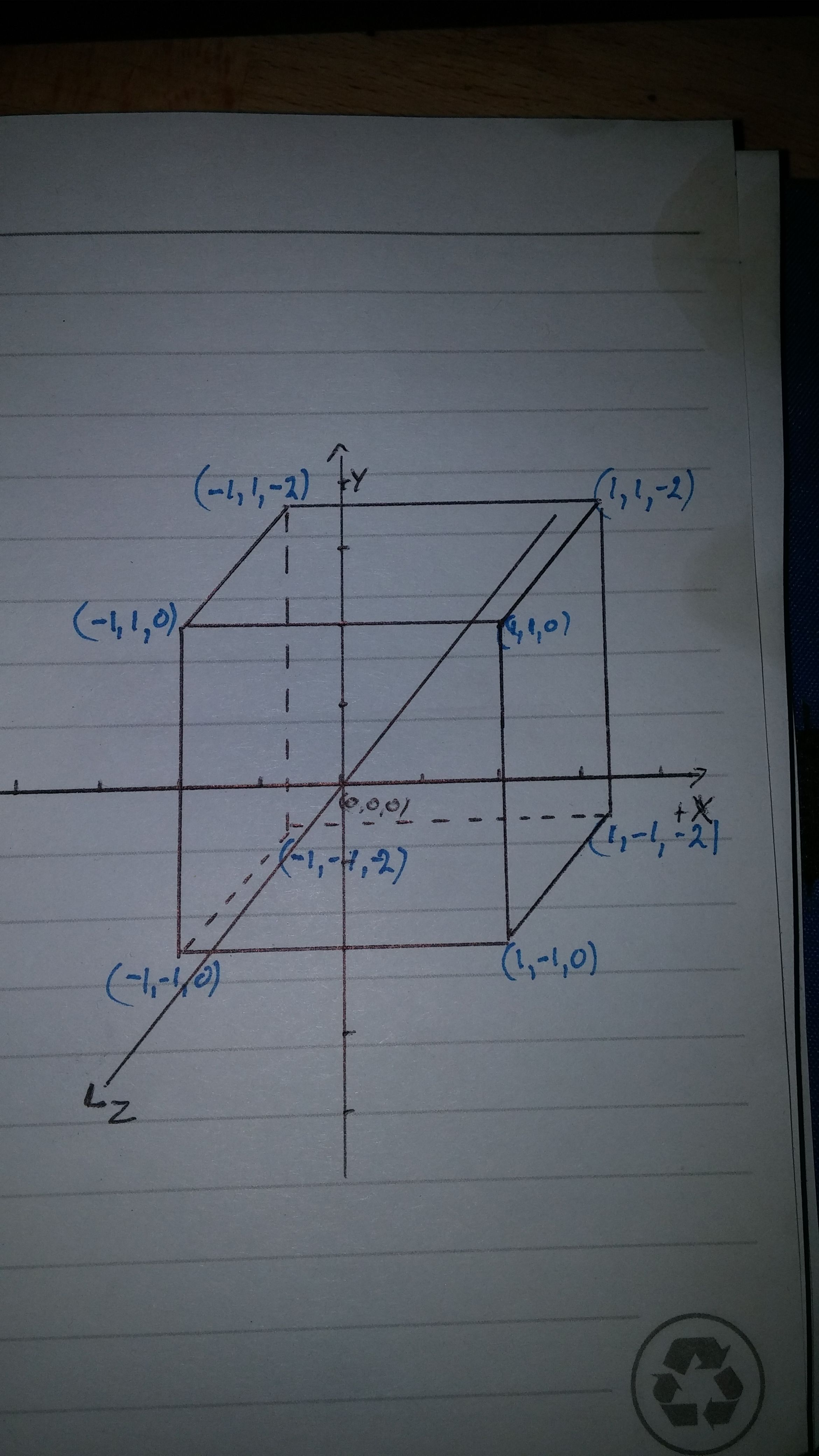
Pretty straightforward, nothing crazy complex there. So, how do we do all that crazy 3D stuff?
Lesson 01 - Example 06: Holy Moley 3D
In order to do 3d, I’m going to make a new base class called ExampleBase3D, derived from ExampleBase. And now we introduce a few new concepts.
Face Culling
Face culling is all about performance. Drawing a triangle is expensive. Drawing over the same area on screen is expensive. So if we can reject a triangle from drawing, we can get a fair bit of a performance boost. So, how does culling work? It’s based on the order in which the vertices of a triangle are described when it faces the viewer. In our previous examples, the position of the viewer is, surprise, surprise, where you sit. Starting with the first vertex of the triangle, the order can either be clockwise or counter-clockwise. OpenGL is smart enough to be able to cull either way. Or not cull at all. So, in our overriden OnLoad() method we have the following:
base.OnLoad(e);

GL.Enable(EnableCap.CullFace);
GL.CullFace(CullFaceMode.Back);
GL.Enable(EnableCap.DepthTest);
GL.Enable(EnableCap.DepthClamp);

GL.DepthMask(true);
In order:
GL.Enable(EnableCap.CullFace)enabled triangle culling.GL.CullFace(CullFaceMode.Back)enable Back-face culling.
The other bits we’ve already covered in other examples.
In the next section we need to talk about the transformation pipeline. We’ve already alluded to it in the past (when talking about 2D rendering) but now it’s time to go into more detail. I love this site’s explaination of it:
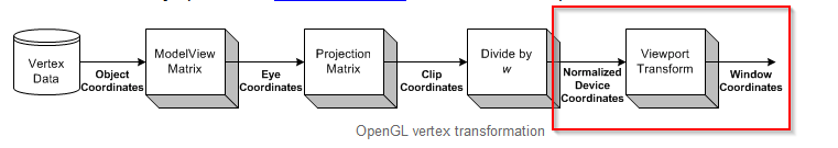
Looking at the image, we have been dealing with Normalized Device Coordinates > Viewport Transform > Windows Coordinates.
We’re dealing with a 3D object (a set of triangles) that needs to be projected onto a 2D surface (the monitor). We do that (and a few other things) through the use of a projection matrix.
What does the projection matrix do? It does a couple of things. First, it defines the aspect ration of the ‘window’ that the 3D objects will be rendered to. Why is that important? Well, assume that we don’t have a square window - that’s very possible. If we don’t into account the non-square-ness of the window, you can end up with stretch or squashed transformed triangles. Additionally, we need to take into account the near and far planes of the rendering ‘Frustum’ - the Frustum is a conical shape, a pyramid, with the top point cut off. Where the top is cut off is your monitor’s screen. The bottom of the pyramid is the furthest that you will want to render. Additionally, you want to track the Field of View (vertical) for rendering. I may go into more detail on this in a later update if need be.
protected override void OnResize(EventArgs e)
{
    base.OnResize(e);

    GL.Viewport(0, 0, Width, Height);
    double aspectRatio = Width / (double)Height;
    float fov = 1.00899694f;
    float nearPlane = 1.0f;
    float farPlane = 100.0f;

    Matrix4 perspective = Matrix4.CreatePerspectiveFieldOfView(fov, (float)aspectRatio, nearPlane, farPlane);
    GL.MatrixMode(MatrixMode.Projection);
    GL.LoadMatrix(ref perspective);
}
So what we have now is a matrix that we can pass all vertices throught to project them onto the screen from world space. If a triangle falls partially outside of the frustum, it’s clipped. If the triangle is completely outside of the frustum, it’s rejected.
Also note that we only update the projection matrix when we resize the window; The projection matrix does not take into account the position of the camera. The reason for that is that the camera doesn’t actually rotate; objects rotate into the camera’s view. More on that later.
If you look at the Camera class, you’ll see that it’s fairly straight forward.
- The constructor takes an eye point.
- The Update rotates around the Y axis
- We feed the rotated eye position into
Matrix4.LookAtto build the modelview matrix. We then feed that into the appropriate matrix slot.
The only other thing to describe is the grid that we draw. This is nothing more than a set of lines, rendered with a bit of antialiasing GL.Hint(HintTarget.LineSmoothHint, HintMode.Nicest); and it’s own modelview matrix GL.PushMatrix();, GL.Translate(dX - grid_size / 2, 0, dZ - grid_size / 2); and GL.PopMatrix();. As always, with the OpenGL state machine, if we need to bracket each state: GL.Enables must have a matching GL.Disable, GL.PushMatrix must have a corresponding GL.PopMatrix.
Summary
That’s about it for this project. I’ll update it as I come across missing bits, clarify more things that I’ve only superficially covered. However, this really was only meant as a refresher in Legacy OpenGL. The next project will go into more ‘modern’ OpenGL (shaders).
I’ve really glossed over a lot of details in this article (OpenGL matrices, Cameras). Rather than overtly ignore it, I’ve included links to, IMO, some great articles on those topics:
- (OpenGL Matrices)[http://www.opengl-tutorial.org/beginners-tutorials/tutorial-3-matrices/]
- (Transformations)[https://open.gl/transformations]
- (OpenGL FAQ)[https://www.opengl.org/archives/resources/faq/technical/transformations.htm]
## Todo
[ ] an example of lighting?
[ ] shadows?